
_page-0001")
Pumps & Mechanical
Instrumentation for Process Control – Basic Requirements
Only logged in customers who have purchased this product may leave a review.
Related books
Centrifugal Pump Application and Optimization
Summary
Centrifugal pumps perform many important functions to control the built environment. The physics and basic mechanics of pumps have not changed substantially in the last century. However, the state of the art in the application of pumps has improved dramatically in recent years. Even so, pumps are still often not well applied, and become common targets in retrocommissioning projects where field assessment and testing can reveal significant energy savings potential from optimizing pump performance. Typically, retrocommissioning finds that pump flow rates do not match their design intent and that reducing flow rates to match load requirements or eliminating unnecessary pressure drops can save energy. As the example below illustrates, decisions made during the design phase have implications throughout the operating life of the building. Although fully optimizing any design will require some effort after installation, the prevalence and magnitude of the savings that are commonly found in retrocommissioning and ongoing commissioning begs the larger question: How much greater would the savings be if pumps were selected and applied optimally during the design phase?

Centrifugal Pump Training
Objectives
Understand pump fundamentals
Understand the probable root causes of degradation or failure associated with various pump problems
Understand the state-of-the-art technologies to upgrade existing designs to achieve improved operation and life
Learn how to determine where a pump is operating and how to modify its performance to achieve optimum performance

Centrifugal and Positive Displacement Pumps
Introduction
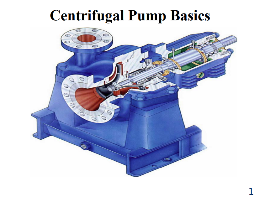
Centrifugal pumps basically consist of a stationary pump casing and an impeller mounted on a rotating shaft. The pump casing provides a pressure boundary for the pump and contains channels to properly direct the suction and discharge flow. The pump casing has suction and discharge penetrations for the main flow path of the pump and normally has small drain and vent fittings to remove gases trapped in the pump casing or to drain the pump casing for maintenance.
Figure 1 is a simplified diagram of a typical centrifugal pump that shows the relative locations of the pump suction, impeller, volute, and discharge. The pump casing guides the liquid from the suction connection to the center, or eye, of the impeller. The vanes of the rotating impeller impart a radial and rotary motion to the liquid, forcing it to the outer periphery of the pump casing where it is collected in the outer part of the pump casing called the volute. The volute is a region that expands in cross-sectional area as it wraps around the pump casing. The purpose of the volute is to collect the liquid discharged from the periphery of the impeller at high velocity and gradually cause a reduction in fluid velocity by increasing the flow area. This converts the velocity head to static pressure. The fluid is then discharged from the pump through the discharge connection.
Centrifugal and Positive Displacement Pumps
Introduction
Centrifugal pumps basically consist of a stationary pump casing and an impeller mounted on a rotating shaft. The pump casing provides a pressure boundary for the pump and contains channels to properly direct the suction and discharge flow. The pump casing has suction and discharge penetrations for the main flow path of the pump and normally has small drain and vent fittings to remove gases trapped in the pump casing or to drain the pump casing for maintenance.
Figure 1 is a simplified diagram of a typical centrifugal pump that shows the relative locations of the pump suction, impeller, volute, and discharge. The pump casing guides the liquid from the suction connection to the center, or eye, of the impeller. The vanes of the rotating impeller impart a radial and rotary motion to the liquid, forcing it to the outer periphery of the pump casing where it is collected in the outer part of the pump casing called the volute. The volute is a region that expands in cross-sectional area as it wraps around the pump casing. The purpose of the volute is to collect the liquid discharged from the periphery of the impeller at high velocity and gradually cause a reduction in fluid velocity by increasing the flow area. This converts the velocity head to static pressure. The fluid is then discharged from the pump through the discharge connection.


Reviews
There are no reviews yet.