

Clarifier Calculations
Source https://www.michigan.gov
Prepared by
Michigan Department of Environmental Quality
Operator Training and Certification Unit
Only logged in customers who have purchased this product may leave a review.
Related products


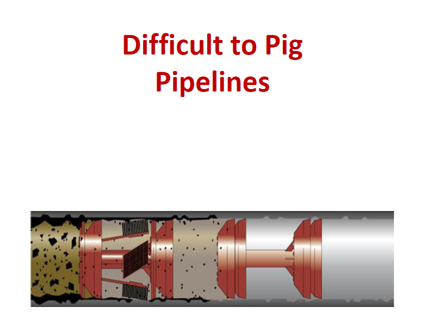
Difficult to Pig Pipelines
Pigging : A widely utilized process which is the act of propelling a properly sized spherical or cylindrical device through the interior of a pipeline by manipulating the pressure & flow of the existing media, or by artificially introduced media or by mechanically pulling the device through the pipeline for the
specific purpose of cleaning, inspecting or distributing inhibitor throughout the pipeline.

Presentation on Fundamentals of Pipeline Design
➢The amount of fluid flow through the pipeline is one of the first items of information required for design
➢ Different industries use pipeline for different purposes. requirements & types of pipe are different
➢ Petroleum industry & natural gas industry use steel pipe with welded joints.
➢ This allows the pipeline to withstand very high pressure, sometimes above 3000 psig
➢ High pressure allow the use of long pipelines, often more then 1000 miles with only a booster pump or station for each pipeline
➢ Some pipelines are designed with some excess capacity or design so capacity can be increased by the addition of compression or pumping horsepower


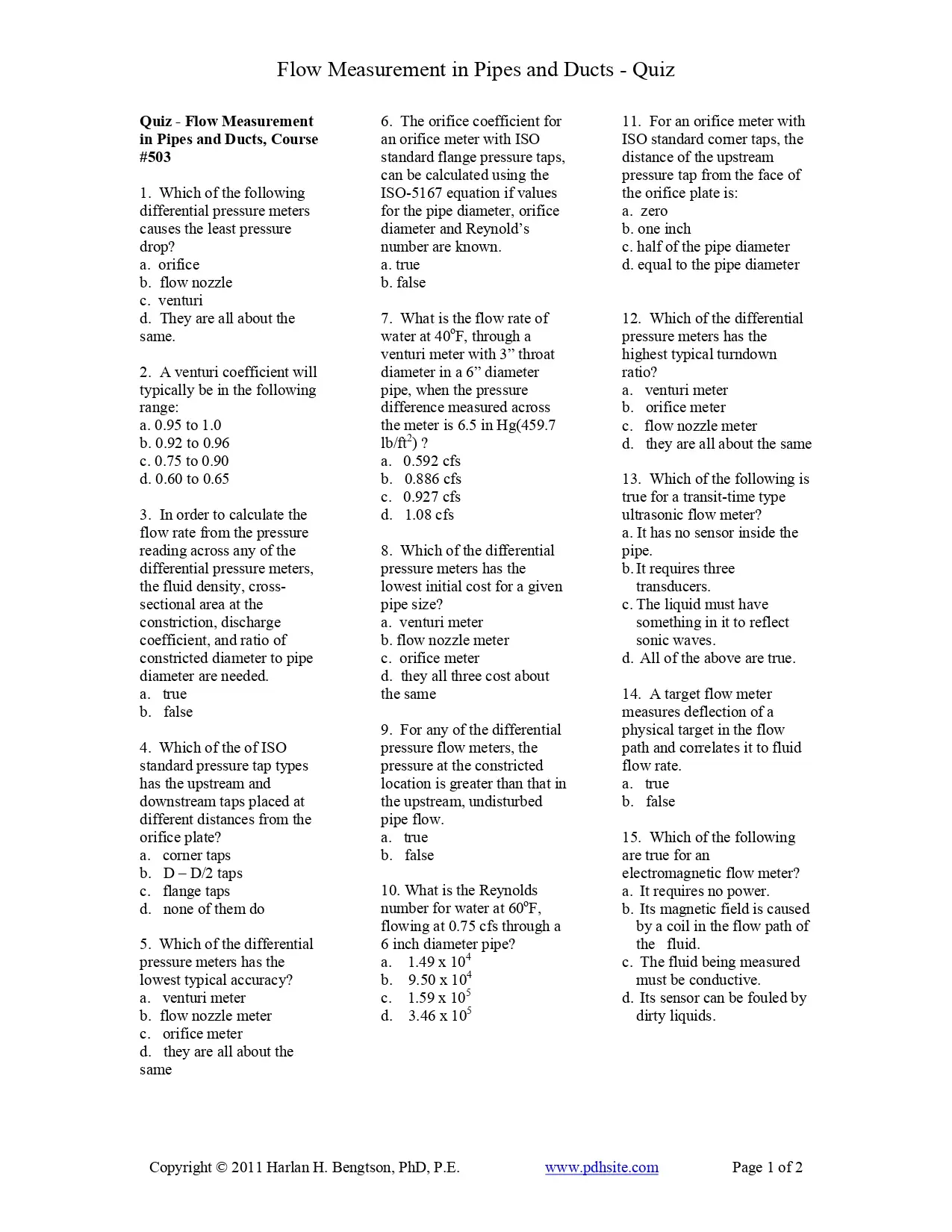
Flow Measurement in Pipes and Ducts Course
This course is about measurement of the flow rate of a fluid flowing under pressure in a closed conduit. This course is intended primarily for mechanical, civil and chemical, environmental, and industrial engineers. Someone completing this course will gain knowledge about twelve different types of meters for measuring fluid flow rate in a closed conduit. They will learn about typical calculations for differential pressure meters and pitot tubes. They will learn the general principles of operation for each type and general advantages and disadvantages of each.


Pipe Flow-Friction Factor Calculations with Excel, Course
Several kinds of pipe flow calculations can be made with the Darcy- Weisbach equation and the Moody friction factor. These calculations can be conveniently carried out with an Excel spreadsheet. Many of the calculations require an iterative solution, so they are especially suitable for an Excel spreadsheet solution. This course includes discussion of the Darcy- Weisbach equation and the parameters in the equation along with the U.S.
and S.I. units to be used. Example calculations and sample Excel spreadsheets for making the calculations are also included. This course is intended primarily for civil engineers, mechanical engineers, chemical engineers, and environmental engineers. After completing this course you will be able to make calculations with the Darcy Weisbach equation and the Moody friction factor equations to calculate several different unknown parameters when sufficient input data is provided. You will also be prepared to use Excel spreadsheets to efficiently make the calculations.

Basic Pipe Stress Analysis Tutorial
It is common practice worldwide for piping designers to route piping by considering mainly space, process and flow constraints (such as pressure drop) and other requirements arising from constructability, operability and reparability. Unfortunately, pipe stress analysis requirements are often not sufficiently considered while routing and supporting piping systems, especially in providing adequate flexibility to absorb expansion/contraction of pipes due to thermal loads. So, when “as designed” piping systems are handed-off to pipe stress engineers for detailed analysis, they soon realize that the systems are “stiff” and suggest routing changes to make the systems more flexible. The piping designers, in turn, make changes to routing and send the revised layout to the pipe stress engineers to check for compliance again. Such “back and forth” design iterations between layout and stress departments continue until a suitable layout and support scheme is arrived at, resulting in significant increase in project execution time, which, in turn, increases project costs. This delay in project execution is further worsened in recent years by increased operating pressures and temperatures in order to increase plant output; increased operating pressures increase pipe wall thicknesses, which, in turn, increase piping stiffnesses further. Such increased operating temperatures applied on “stiffer” systems increase pipe thermal stresses and support loads. So, it is all the more important to make the piping layout flexible at the time of routing.
Reviews
There are no reviews yet.