

The New Zealand Pipe Inspection Manual 3rd Edition has been prepared in order to provide:
• An overview of the tasks that can be completed using Closed Circuit Television (CCTV) and how these activities can be used to manage wastewater and stormwater assets.
• A standardised set of codes for recording observations noted during CCTV inspections.
• An outline of good practice procedures for carrying out CCTV inspections and for processing and analysing the information collected.
• Standard Technical Specifications and Model Conditions of Contract for use when engaging CCTV contractors.
Only logged in customers who have purchased this product may leave a review.
Related products
Introduction to Piping Design
• As per Merriam Webster dictionary , the pipe is a long tube or hollow body for conducting a liquid, gas, or finely divided solid.
• Technically : The pipe Is a beam , which acts as pressure vessel and transfer fluids.
Introduction to Piping Design
• As per Merriam Webster dictionary , the pipe is a long tube or hollow body for conducting a liquid, gas, or finely divided solid.
• Technically : The pipe Is a beam , which acts as pressure vessel and transfer fluids.
Corrosion Mitigation of Metal & Concrete Pipes and Structures
Purpose:
This document has been prepared to provide instruction and information on how South East Water (SEW) achieves the design life of its assets through prudent corrosion control measures. While this document outlines the standards which apply to each risk control and may provide some general information and reinforcement of critical aspects of each standard, it is not intended that this document replicate technical information contained in the standards.


Cathodic Protection Part 1 – Pipelines
SA Water is responsible for operation and maintenance of an extensive network of buried pipelines. Cathodic Protection (CP) is applied to a large proportion of those buried assets which assists with the management of external pipeline corrosion and is therefore and an important asset management tool to greatly increase asset life. This Standard has been developed to assist in the design, maintenance, construction, and management of SA Water’s pipeline CP infrastructure. The purpose of this Standard is to detail the requirements for each phase of a pipeline CP project from design, construction and commissioning, to maintenance and monitoring to ensure a consistent approach is achieved independent of the delivery model of a project, its location, project ownership or other influences.

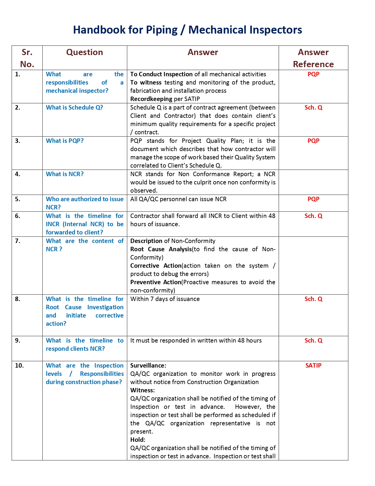
Inspect New Piping
Piping systems are like arteries and veins in the oil industry. Piping systems comprise of pipes, flanges, bolting, gaskets, valves etc. They also include pipe hangers, supporting elements and other items necessary to prevent over pressurization and over stressing of the pressure containing components. Hence, one can say that pipe section when fitted with valves and other mechanical equipment and properly supported by hangers and supports are called piping.

Basic Pipe Stress Analysis Tutorial
It is common practice worldwide for piping designers to route piping by considering mainly space, process and flow constraints (such as pressure drop) and other requirements arising from constructability, operability and reparability. Unfortunately, pipe stress analysis requirements are often not sufficiently considered while routing and supporting piping systems, especially in providing adequate flexibility to absorb expansion/contraction of pipes due to thermal loads. So, when “as designed” piping systems are handed-off to pipe stress engineers for detailed analysis, they soon realize that the systems are “stiff” and suggest routing changes to make the systems more flexible. The piping designers, in turn, make changes to routing and send the revised layout to the pipe stress engineers to check for compliance again. Such “back and forth” design iterations between layout and stress departments continue until a suitable layout and support scheme is arrived at, resulting in significant increase in project execution time, which, in turn, increases project costs. This delay in project execution is further worsened in recent years by increased operating pressures and temperatures in order to increase plant output; increased operating pressures increase pipe wall thicknesses, which, in turn, increase piping stiffnesses further. Such increased operating temperatures applied on “stiffer” systems increase pipe thermal stresses and support loads. So, it is all the more important to make the piping layout flexible at the time of routing.

Pipe Flow-Friction Factor Calculations with Excel, Course
Several kinds of pipe flow calculations can be made with the Darcy- Weisbach equation and the Moody friction factor. These calculations can be conveniently carried out with an Excel spreadsheet. Many of the calculations require an iterative solution, so they are especially suitable for an Excel spreadsheet solution. This course includes discussion of the Darcy- Weisbach equation and the parameters in the equation along with the U.S.
and S.I. units to be used. Example calculations and sample Excel spreadsheets for making the calculations are also included. This course is intended primarily for civil engineers, mechanical engineers, chemical engineers, and environmental engineers. After completing this course you will be able to make calculations with the Darcy Weisbach equation and the Moody friction factor equations to calculate several different unknown parameters when sufficient input data is provided. You will also be prepared to use Excel spreadsheets to efficiently make the calculations.


Hydraulic Study For The New Cairo Raw Water Pipeline
phase is expected to be completed by the end of 2011. The system consists of one raw water intake pump station (IPS), three booster pump stations (BPS 2, 3, and 4), and multiple parallel 2200-millimeter (mm) and 2600-mm diameter pipelines that run approximately 30 kilometers (km) from the Nile River to the newly constructed New Cairo Potable Water Treatment Plant (WTP). Construction will be completed in eight pump installation phases, with design flows ranging from 6 cubic meters per second (m3/sec) at Phase 1 to an ultimate flow of 48 m3 Because the pumping capacity required for Phases 5-8 is to be supplied by a parallel system of pump stations and pipelines that mirror Phases 1-4 (with identical hydraulics and capacities), the following report is based on analysis of Phases 1-4 only. The ultimate flow rate for Phase 4 is 24 m /sec at Phase 8.

Reviews
There are no reviews yet.