

Pumps & Mechanical
A Case Study Of Vibration In Positive Displacement Pump Systems
A Case Study Of Vibration In Positive Displacement Pump Systems
Source: https://turbolab.tamu.edu
Prepared By: Trenton Cook, Sarah Simons
Positive displacement pump systems can experience high piping vibrations. System vibration can have many root causes- including underdamped fluid pulsations, mechanical resonance, and poor skid design.
Only logged in customers who have purchased this product may leave a review.
Related books
Centrifugal Pump Analysis
Introduction
Centrifugal pumps are used to increase pressure in a liquid for the purpose of transporting the liquid through piping and other devices for use in an industrial process. With the higher pressure, the liquid can be transported in short or long pipelines for delivery to an ultimate destination. Examples include water pipelines, refined petroleum and crude oil pipelines.
The pressure generated by the pump is gradually depleted as the liquid flows through the pipeline, due to friction in the pipe, as well as any elevation increase from the point of origin to the destination point. The liquid as it enters the pump has a certain amount of energy, due to its initial pressure (pressure energy), position (potential energy) and its velocity (kinetic energy). The potential energy depends on the location of the liquid from some datum, such as sea level. The kinetic energy is due to the motion of the liquid. The sum of three components is the total energy of the liquid. As the liquid comes out of the pump, energy is imparted by the rotating element (impeller) in the pump and the liquid pressure increases. The velocity of the liquid also changes from that at the pump inlet. In a centrifugal pump, the liquid is accelerated by centrifugal force during its passage through the rotating pump impeller and, finally at the exit, the kinetic energy is converted to pressure energy as it exits the pump volute into the discharge piping.
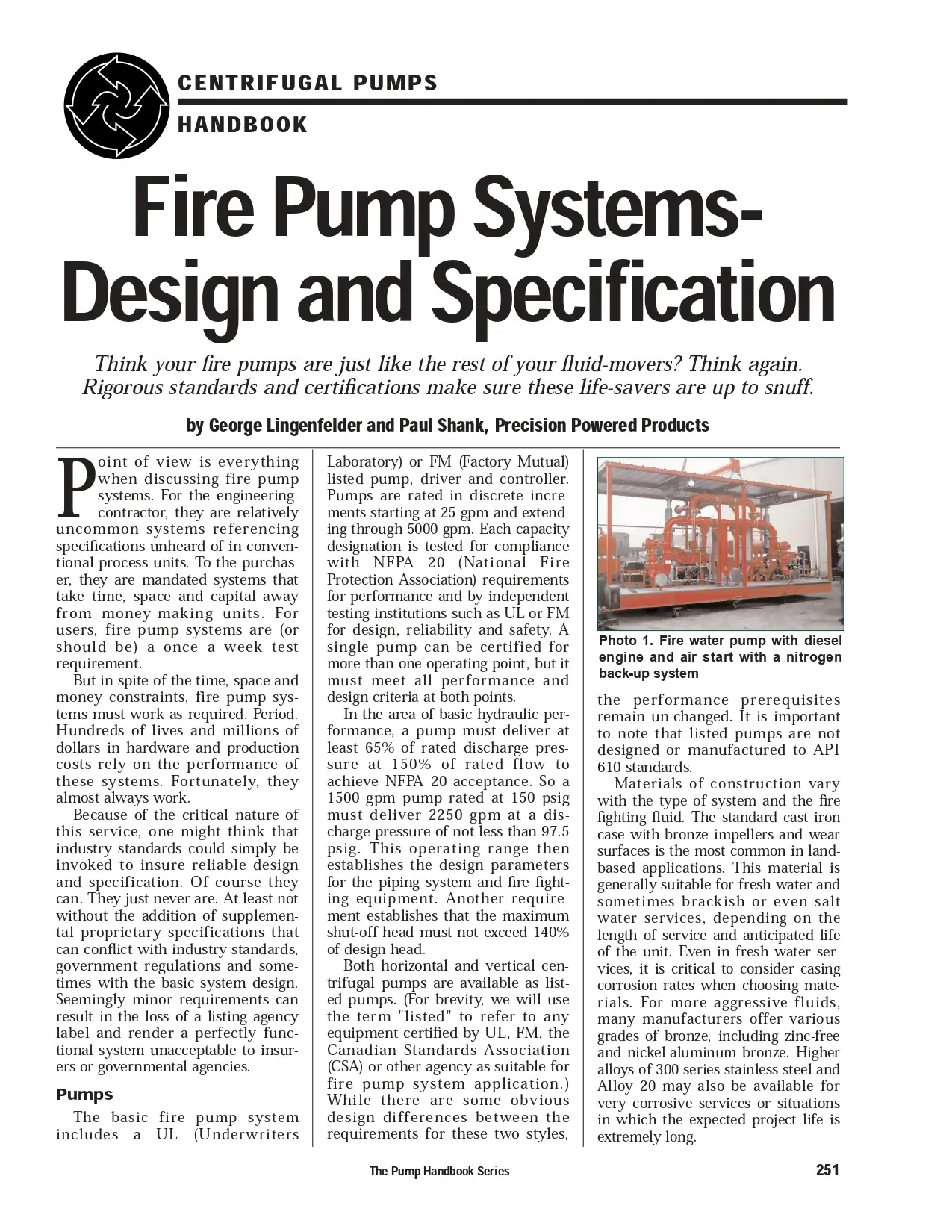
Fire Pump Systems Design and Specification
Think your fire pumps are just like the rest of your fluid movers? Think again. Rigorous standards and certifications make sure these life-savers are up to snuff
Fire Pump Systems Design and Specification
Think your fire pumps are just like the rest of your fluid movers? Think again. Rigorous standards and certifications make sure these life-savers are up to snuff

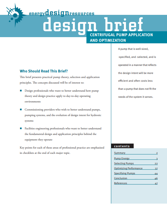
Centrifugal Pump Application and Optimization
Summary
Centrifugal pumps perform many important functions to control the built environment. The physics and basic mechanics of pumps have not changed substantially in the last century. However, the state of the art in the application of pumps has improved dramatically in recent years. Even so, pumps are still often not well applied, and become common targets in retrocommissioning projects where field assessment and testing can reveal significant energy savings potential from optimizing pump performance. Typically, retrocommissioning finds that pump flow rates do not match their design intent and that reducing flow rates to match load requirements or eliminating unnecessary pressure drops can save energy. As the example below illustrates, decisions made during the design phase have implications throughout the operating life of the building. Although fully optimizing any design will require some effort after installation, the prevalence and magnitude of the savings that are commonly found in retrocommissioning and ongoing commissioning begs the larger question: How much greater would the savings be if pumps were selected and applied optimally during the design phase?
Chapter Two Reciprocating Compressors Construction Details
Reciprocating Compressors Construction Details
In general, materials for the construction of the compressor and auxiliaries are normally the manufacturer's standard for the specified operating conditions except as required by the datasheet or certain specifications.
Chapter10. Compressors
Main Types of Compressors
The compressor is the heart of a mechanical refrigeration system.
There is the need for many types of compressors because of the variety of refrigerants and the capacity, location and application of the systems.
Generally, the compressor can be classified into two basic types: positive displacement and roto-dynamic.
Chapter One Classification Of Pumps
What Is a Pump?
A pump is a machine or device for raising, transferring, or compressing fluids. Pumps represent the largest single use of power in the industry (31%) by motor-driven equipment. Process variables, including pressure and flow of gases and liquids, have long been regulated using mechanical clutches, throttles, and adjustable inlet guide vanes. Pumps often operate as a variable torque load, a load that increases as the speed increases. These mechanisms waste energy, require frequent maintenance, and provide inaccurate control.
Centrifugal and Positive Displacement Pumps
Introduction
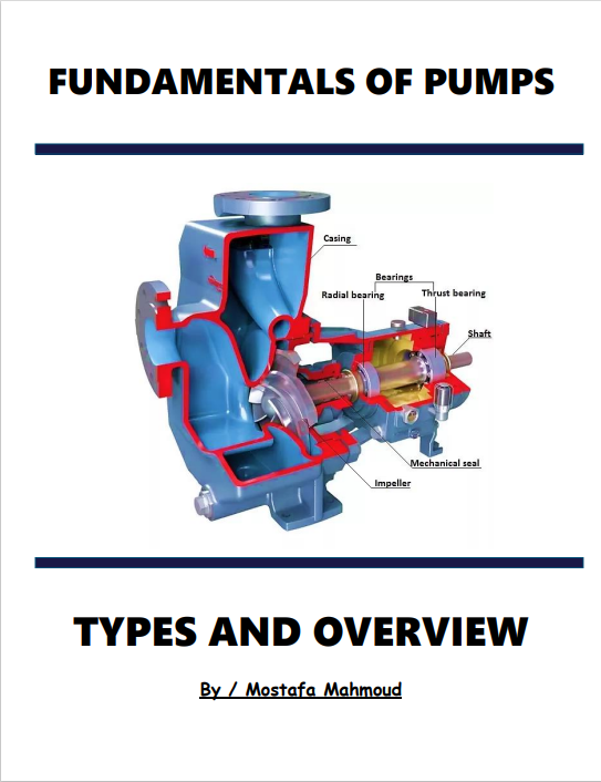
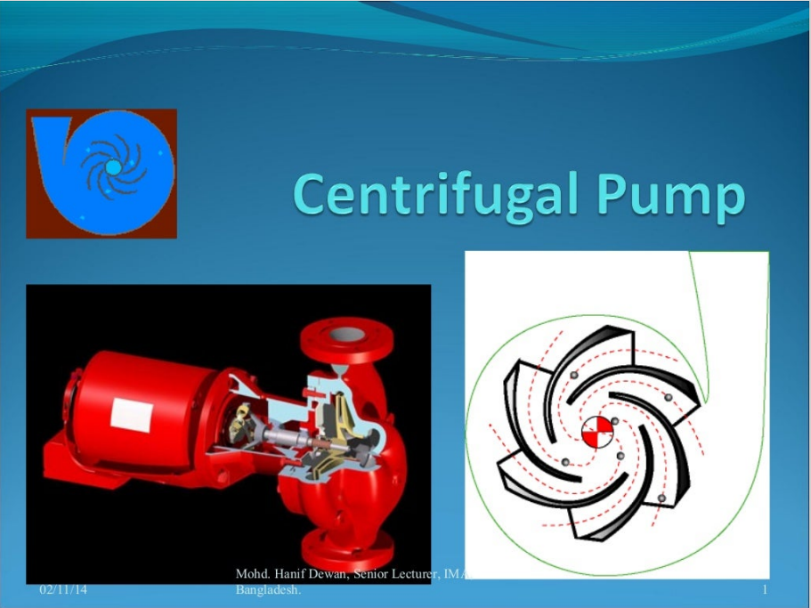
Centrifugal pumps basically consist of a stationary pump casing and an impeller mounted on a rotating shaft. The pump casing provides a pressure boundary for the pump and contains channels to properly direct the suction and discharge flow. The pump casing has suction and discharge penetrations for the main flow path of the pump and normally has small drain and vent fittings to remove gases trapped in the pump casing or to drain the pump casing for maintenance.
Figure 1 is a simplified diagram of a typical centrifugal pump that shows the relative locations of the pump suction, impeller, volute, and discharge. The pump casing guides the liquid from the suction connection to the center, or eye, of the impeller. The vanes of the rotating impeller impart a radial and rotary motion to the liquid, forcing it to the outer periphery of the pump casing where it is collected in the outer part of the pump casing called the volute. The volute is a region that expands in cross-sectional area as it wraps around the pump casing. The purpose of the volute is to collect the liquid discharged from the periphery of the impeller at high velocity and gradually cause a reduction in fluid velocity by increasing the flow area. This converts the velocity head to static pressure. The fluid is then discharged from the pump through the discharge connection.
Centrifugal and Positive Displacement Pumps
Introduction
Centrifugal pumps basically consist of a stationary pump casing and an impeller mounted on a rotating shaft. The pump casing provides a pressure boundary for the pump and contains channels to properly direct the suction and discharge flow. The pump casing has suction and discharge penetrations for the main flow path of the pump and normally has small drain and vent fittings to remove gases trapped in the pump casing or to drain the pump casing for maintenance.
Figure 1 is a simplified diagram of a typical centrifugal pump that shows the relative locations of the pump suction, impeller, volute, and discharge. The pump casing guides the liquid from the suction connection to the center, or eye, of the impeller. The vanes of the rotating impeller impart a radial and rotary motion to the liquid, forcing it to the outer periphery of the pump casing where it is collected in the outer part of the pump casing called the volute. The volute is a region that expands in cross-sectional area as it wraps around the pump casing. The purpose of the volute is to collect the liquid discharged from the periphery of the impeller at high velocity and gradually cause a reduction in fluid velocity by increasing the flow area. This converts the velocity head to static pressure. The fluid is then discharged from the pump through the discharge connection.
Reviews
There are no reviews yet.