

Piping systems are like arteries and veins in the oil industry. Piping systems comprise of pipes, flanges, bolting, gaskets, valves etc. They also include pipe hangers, supporting elements and other items necessary to prevent over pressurization and over stressing of the pressure containing components. Hence, one can say that pipe section when fitted with valves and other mechanical equipment and properly supported by hangers and supports are called piping.
Only logged in customers who have purchased this product may leave a review.
Related products


Pipe Installation Handbook
Installing fiberglass pipe is easier than installing carbon steel, stainless steel, and lined steel due to its light weight. Learning the proper methods to prepare and make-up bell & spigot joints can help ensure the reliability and long-term performance of your piping system. We offer the TQI Plus (ASME B31.3) Fabrication and Assembly certification program. Qualified Field Service Representatives train fabrication and assembly crews, conduct and supervise
fabrication work, and inspect work in progress. For complete information concerning these training seminars, contact your local distributor or NOV Fiber Glass Systems.

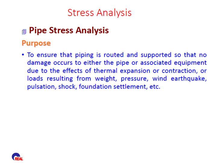
Pipe Stress Analysis
• To ensure that piping is routed and supported so that no damage occurs to either the pipe or associated equipment due to the effects of thermal expansion or contraction, or loads resulting from weight, pressure, wind earthquake, pulsation, shock, foundation settlement, etc.
Pipe Stress Analysis
• To ensure that piping is routed and supported so that no damage occurs to either the pipe or associated equipment due to the effects of thermal expansion or contraction, or loads resulting from weight, pressure, wind earthquake, pulsation, shock, foundation settlement, etc.

Flow Measurement in Pipes and Ducts
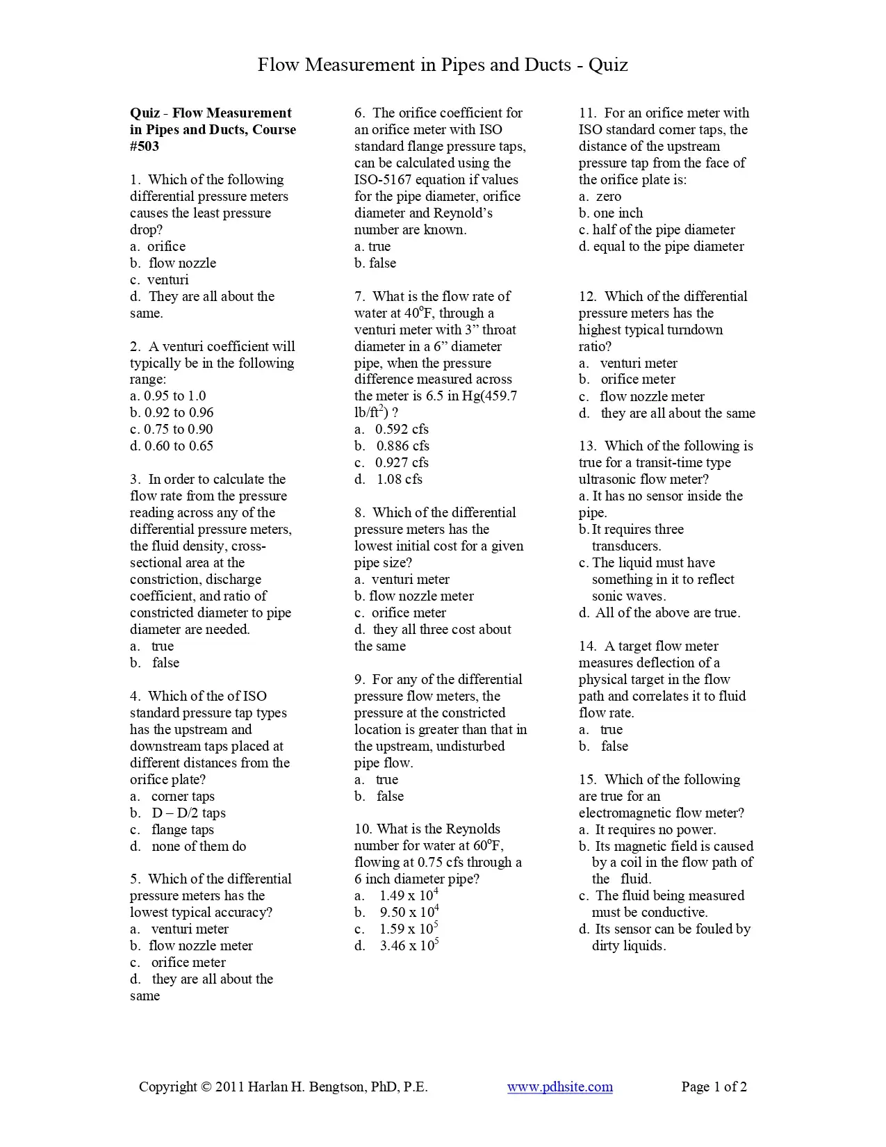
This course is about measurement of the flow rate of a fluid flowing under pressure in a closed conduit. The closed conduit is often circular, but also may be square or rectangular (such as a heating duct) or any other shape. The other major category of flow is open channel flow, which is the flow of a liquid with a free surface open to atmospheric pressure. Measurement of the flow rate of a fluid flowing under pressure, is carried out for a variety of purposes, such as billing for water supply to homes or businesses or, for monitoring or process control of a wide variety of industrial processes that involve flowing fluids. Several categories of pipe flow measurement devices will be described and discussed, including some associated calculations.
Flow Measurement in Pipes and Ducts
This course is about measurement of the flow rate of a fluid flowing under pressure in a closed conduit. The closed conduit is often circular, but also may be square or rectangular (such as a heating duct) or any other shape. The other major category of flow is open channel flow, which is the flow of a liquid with a free surface open to atmospheric pressure. Measurement of the flow rate of a fluid flowing under pressure, is carried out for a variety of purposes, such as billing for water supply to homes or businesses or, for monitoring or process control of a wide variety of industrial processes that involve flowing fluids. Several categories of pipe flow measurement devices will be described and discussed, including some associated calculations.

Hydraulic Study For The New Cairo Raw Water Pipeline
phase is expected to be completed by the end of 2011. The system consists of one raw water intake pump station (IPS), three booster pump stations (BPS 2, 3, and 4), and multiple parallel 2200-millimeter (mm) and 2600-mm diameter pipelines that run approximately 30 kilometers (km) from the Nile River to the newly constructed New Cairo Potable Water Treatment Plant (WTP). Construction will be completed in eight pump installation phases, with design flows ranging from 6 cubic meters per second (m3/sec) at Phase 1 to an ultimate flow of 48 m3 Because the pumping capacity required for Phases 5-8 is to be supplied by a parallel system of pump stations and pipelines that mirror Phases 1-4 (with identical hydraulics and capacities), the following report is based on analysis of Phases 1-4 only. The ultimate flow rate for Phase 4 is 24 m /sec at Phase 8.

Pipe Flow-Friction Factor Calculations with Excel, Course
Several kinds of pipe flow calculations can be made with the Darcy- Weisbach equation and the Moody friction factor. These calculations can be conveniently carried out with an Excel spreadsheet. Many of the calculations require an iterative solution, so they are especially suitable for an Excel spreadsheet solution. This course includes discussion of the Darcy- Weisbach equation and the parameters in the equation along with the U.S.
and S.I. units to be used. Example calculations and sample Excel spreadsheets for making the calculations are also included. This course is intended primarily for civil engineers, mechanical engineers, chemical engineers, and environmental engineers. After completing this course you will be able to make calculations with the Darcy Weisbach equation and the Moody friction factor equations to calculate several different unknown parameters when sufficient input data is provided. You will also be prepared to use Excel spreadsheets to efficiently make the calculations.
Reviews
There are no reviews yet.